About - Publications - Blog
Maximum Efficiency for a Capacitive Wireless Power Transfer System with Multiple Transmitters or Receivers (MISO - SIMO)
Summary
Typical wireless power transfer systems on the market use a single transmitter to charge a single receiver at a time (SISO: single-input single-output). However, it can be expected that the need will arise to charge multiple devices at once by a single transmitter (SIMO: single-input multiple-output), or to charge a single receiver by multiple transmitters (MISO: multiple-input single output). But adding extra transmitters or receivers influences the system efficiency. By impedance matching, the loads of the system can be adjusted to maximize the efficiency, regardless of the number of transmitters or receivers. We present the analytical solution for achieving maximum system efficiency for MISO and SIMO capacitive wireless power transfer.
References
Ben Minnaert, Alessandra Costanzo, Giuseppina Monti, Mauro Mongiardo,
Capacitive Wireless Power Transfer with Multiple Transmitters: Efficiency
Optimization. Energies 2020, 13, 3482.
Paper: [pdf]
Ben Minnaert, Mauro Mongiardo, Alessandra Costanzo and Franco Mastri,
Maximum Efficiency Solution for Capacitive Wireless Power Transfer with
N Receivers. Wireless Power Transfer, 1-11. doi:10.1017/wpt.2020.9
Paper: [Journal
website] [pdf]
Introduction
Wireless power transfer from multiple transmitters to a single receiver
(MISO:
multiple-input single-output, figure 1) can be beneficial compared to
the single-transmitter configuration (SISO):
- First, multiple transmitters targeting a single receiver results in a certain robustness against misalignment or mispositioning of the receiver. This extends the mobility of the receiver. If, for example, multiple transmitters are present in a planar configuration, the power transfer can be realized for a wide possibility of planar receiver positions.
- Second, the above implies that the use of multiple transmitters can extend the range of the wireless power transfer.
- A decentralization of the transmitters can possibly facilitate high-power energy transfer by applying multiple cheaper low-power input supplies.
- Multiple transmitters make the WPT system less vulnerable to foreign blocking objects.
- Last but not least, as will be shown in this work, multiple transmitters allow for a higher system efficiency for given coupling coefficients since they allow for a higher degree of freedom for the power input distribution.

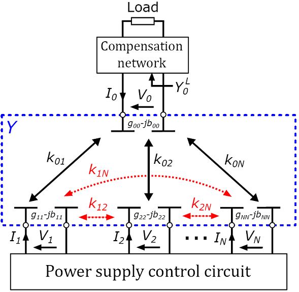
Figure 1:Schematic overview of a capacitive wireless power transfer system with multiple transmitters and a single receiver (MISO).
Also capacitive wireless power transfer with multiple receivers (SIMO) can for certain application be beneficial. Since the plates of an electric coupled link are simple and cheap electrodes, multiple receivers can be powered at once by a single transmitter: large transmitter plates can cover multiple smaller receiver plates.
A straightforward application is the simultaneously charging of low power consumer devices on a large surface area. A more futuristic example is the wireless charging of electric taxis while queuing: as the taxis await their customers at a designated area, a transmitter plate below the ground charges the vehicles wirelessly (Figure 2).

Figure 2: A futuristic example application of SIMO capacitive wireless power transfer: as multiple (electric) taxis are queuing at a designated area (e.g., at a station), a transmitter plate below the ground transfers energy to a receiver plate at the bottom of the vehicles, by means of the electric field E.
Results for MISO
In order to practically achieve the maximum attainable efficiency, three conditions must be met simultaneously (more details here):
- The value of the input current sources (Figure 3a) must be invers proportional to the coupling factor between the source and the receiver.
- Specific shunt susceptances must be connected to each input port (Figure 3a) in order to eliminate the undesired cross-coupling between the transmitters.
- The output load conductance and susceptance must equal specific values,
proportional to the conductance and susceptance of the receiver, respectively
(Figure 3b).

Figure 3: Maximum-efficiency solution for (a) the transmitter ports with generator and internal shunt admittance, and (b) the receiver port with the optimal load susceptance and load conductance.
Additionally, by conjugate-matching the internal shunt admittance of
the generators,
the maximum-efficiency solution coincides with the configuration that
maximizes the output power
Moreover, the maximum achievable efficiency, the optimal loads, and the
optimal input currents are independent on the cross-coupling between the
transmitters, since this unwanted cross-coupling can be entirely annihilated
with transmitter shunt susceptances. As a result, it is possible
to increase the system efficiency by adding more transmitters,
and compensating every time for transmitter cross-coupling.
Results for SIMO
Similar conclusions can be drawn for the SIMO configuration (more details here):
- Both the optimal load conductance and load capacitance of the n-th
receiver are
proportionate to the parasitic conductance of this n-th receiver. As well for coupled as uncoupled receivers, the optimal conductances assume the same value and are independent on the coupling between the receivers. - It was found that capacitors can be inserted into the network as load susceptances to compensate for any cross-coupling between different receivers. This implies that the cross-coupling between the receivers does not influence the maximum efficiency.
- The maximum achievable efficiency monotonically increases with the
number of
receivers, regardless of the coupling strength between the receivers.