About - Publications - Blog
Coupling-Independent Capacitive Wireless Power Transfer
Summary
In a lot of applications, the coupling between transmitter and receiver of a wireless power transfer system is variable. In this work, we present a solution to keep the power transfer and efficiency constant, even when the receiver is moving with regard to the transmitter, i.e. for non-static applications. We achieve coupling-independent wireless power transfer by changing the operating frequency, depending on the coupling. This was already done for inductive systems, but we present a solution for capacitive wireless power transfer.
Reference
Ben Minnaert, Franco Mastri, Nobby Stevens, Alessandra Costanzo and
Mauro Mongiardo, Coupling-Independent Capacitive Wireless Power Transfer
Using Frequency Bifurcation. Energies, 11, (2018) art.nr. 1912.
Paper: [pdf]
Goal
A promising wireless power transfer (WPT) technique that has already entered as well the consumer as the industrial market is inductive wireless power transfer (IPT). This near-field technique uses a varying magnetic field to transfer energy from a transmitter coil to a coupled receiver coil. Another near-field technique is capacitive wireless power transfer (CPT) that uses the electric field to transfer energy from a transmitter plate to a receiver plate. However, CPT has not yet significantly entered the market and its technology is not as maturely developed as IPT. Compared to IPT, CPT has the advantage to transfer energy through metal, and is expected to realize WPT at a lower cost and weight than IPT.
In general, a practical WPT system design will pursue one of two options, depending on the application. It will either
- optimize the efficiency of the system, e.g., for the wireless charging of high power applications as electric vehicles.
- optimize the power transfer to the load, e.g., charging transcutaneous biomedical implants.
Two approaches exist to achieve these solutions:
- In a fixed frequency design, an impedance compensation network is added to realize optimum efficiency or power transfer at the operating frequency. The value of its components are independent of the coupling between transmitter and receiver, but for each different value of the coupling, another optimal load value applies. This approach has the advantage of realizing optimum efficiency or power transfer at a fixed operating frequency. However, at fluctuating coupling, the load value has to change to retain the optimal conditions.
- In a frequency agile design, optimum efficiency or power transfer can be achieved for a fixed load value, even at fluctuating coupling. With the same impedance compensation network as in the fixed frequency design, a constant efficiency or power transfer can be realized by changing the operating frequency, depending on the coupling between transmitter and receiver.
For applications where the coupling is variable in time, the latter scheme is preferred.
An analytical solution for realizing the frequency agile design by applying frequency bifurcation for inductive wireless power transfer already exists. It allows for a coupling-independent IPT system by sweeping the frequency to realize a purely resistive input impedance.
However, to our knowledge, no analytic coupling-independent solution was presented yet for CPT. In this work, we present the coupling-independent CPT and compare the solution to IPT.
Results
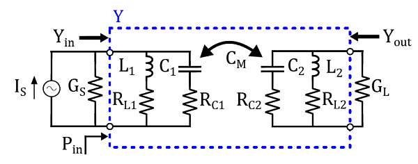
We consider a general, static CPT system. The capacitive link can be represented by an equivalent circuit, given by capacitances C1 and C2, coupled by their mutual capacitance CM (Figure 1).Based on Norton's theorem, we represent the supply of the transmitter by a time-harmonic current source IS with shunt conductance GS. Power is wireless transmitted to the load conductance GL. We create resonant circuits with chosen angular frequency ω0 by adding appropriate shunt inductances L1 and L2 to the transmitter and receiver.
The inductor and capacitor losses are represented by the series resistances RL1, RL2, RC1 and RC2 as indicated on Figure 1.

Figure 1: Equivalent circuit representation of a general CPT system, indicating the input admittance Yin, output admittance Yout, and input power Pin.
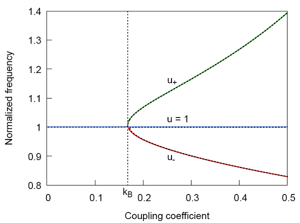
The imaginary part of the input admittance is zero if the frequency equals the resonant angular frequency ω0. This frequency is called the main resonant frequency. However, when the coupling is above a certain bifurcation coupling kB, other frequencies exist where the imaginary part of the input admittance is zero. These frequencies are called the secondary resonant frequencies.

Figure 2:The main resonant frequency (normalized frequency u=1) and the secondary frequencies u± as function of the coupling coefficient k for the example configuration. Frequency bifurcation occurs for a coupling factor k higher than the bifurcation coupling kB.
Figure 2 shows the normalized frequency as function of the coupling coefficient k for an example configuration.

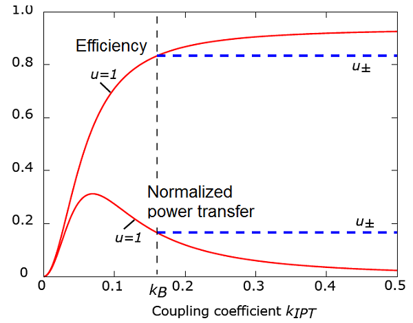
Figure 3: The efficiency and normalized power transfer at the main resonant frequency (u=1) and the secondary resonant frequencies u±, as function of the coupling coefficient k for an example CPT configuration.
Figure 3 shows the efficiency and normalized power transfer as function of the coupling factor, as well at the main resonance (normalized frequency u=1) as at the secondary frequencies (u+ and u-). Notice that the values for the secondary frequencies are only valid for a coupling higher than the bifurcation coupling kB. When operating at u±, both the efficiency and the power transfer remain fairly constant for varying coupling. Notice the advantage of the coupling-independent mode for CPT applications: compared to the main resonant frequency, we obtain a higher power transfer to the load for u± at the expense of only a small reduction in efficiency (in particular for u+).

Figure 4: Equivalent circuit representation of a general IPT system.
Comparison to IPT
Finally, Figure 5 shows the results for the IPT circuit of Figure 4. For IPT, both the efficiency and power transfer remain perfectly constant at the secondary frequencies, i.e. we have a perfect coupling-independent regime.

Figure 5: The efficiency and normalized power transfer at the main resonant frequency (u=1) and the secondary resonant frequencies u±, as function of the coupling coefficient k for an example IPT configuration.
For CPT, a perfect independent coupling is not attained. However, the change in the efficiency and power transfer is almost negligible, resulting in a near independent coupling for practical WPT applications.