About - Publications - Blog
Capacitive wireless power transfer with multiple transmitters and receivers
Summary
Wireless power transfer from one transmitter to multiple receivers through inductive coupling is slowly entering the market. However, for certain applications, capacitive wireless power transfer using electric coupling might be preferable. In this work, we determine closed-form expressions for a capacitive wireless power transfer system with either one transmitter and two receivers, or two transmitters and one receiver. We determine the optimal solution for achieving either maximum power transfer or maximum system efficiency. We demonstrate that coupled receivers (or transmitters) can be compensated by introducing susceptances which have the same value for as well the maximum power as the maximum efficiency configuration.
References
Ben Minnaert and Nobby Stevens. Optimal Analytical Solution for a
Capacitive Wireless Power Transfer System with One Transmitter and Two
Receivers. Energies, 10 (9), (2017) art.nr. 1444.
Paper: [pdf]
Ben Minnaert and Nobby Stevens. Power maximization for capacitive
wireless power transfer with two transmitters and one receiver. MTT-S
International Wireless Symposium (IWS), 2018 IEEE. Chengdu, China, 6-10
May 2018, pp. 1-4.
Paper: [pdf]
Introduction
Capacitive wireless power transfers uses the electric field as medium to transfer energy from a transmitter to a receiver. Up until now, applications are limited to one transmitter and one receiver. However, in the future, applications with multiple transmitters and/or receivers may arise. Consider for example Fig. 1: a transmitter plate, located under a road, wirelessly charges two cars at the same time while the cars are driving.

Figure 1: One transmitter under the road wirelessly charges two driving vehicles at the same time.
But also multiple transmitters are possible. In Fig. 2, for example, two transmitter plates wirelessly charge two driving cars.

Figure 2: Two transmitters under the road wirelessly charges two driving vehicles at the same time.
A general capacitive wireless power transfer system with one transmitter and two receivers is shown in Fig. 3. Two large transmitter plates are used. In this way, the receivers (represented by the four receiver plates) have more degrees of lateral freedom to move, i.e. even when the receiver plates laterally move, wireless charging can continue unaltered.
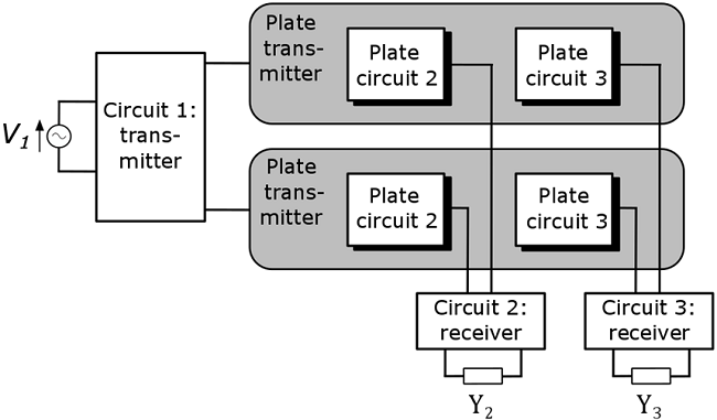
Figure 3:A general capacitive wireless power transfer system with one transmitter and two receivers. V1 is the voltage supply. Y1 and Y2 are the admittances of the loads of receiver 1 and 2, respectively.
Results
The equivalent circuit of Fig. 3 is shown in Fig. 4: on the left, the transmitter is depicted. On the right, the two receivers with admittance loads Y2 and Y3 are shown. The coupling between the transmitter and the receivers is given by the mutual capcitance C12 and C13. However, a non-negligible coupling between the receivers might be present, represented by the mutual coapacitance C23.
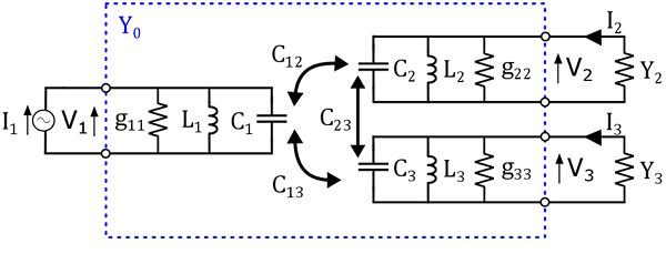
Figure 4: Equivalent circuit of a capacitive wireless power transfer network with one transmitter and two receivers.
In order to maximize the amount of power transferred to both receivers, it is necessary that the loads Y2 and Y3 have a certain value (i.e., G2power and G3power), dependent on the circuit parameters (Fig. 5, details in references above). However, it is only possible to achieve maximum power transfer if certain susceptances B2 and B3 are added in parallel to the receivers. These susceptances are capacitances (CB2 and CB3) and are linearly dependent on the coupling between the both receivers. In other words, these capacitances compensate for the coupling between both receivers. If there is no coupling between both receivers (i.e. C23=0), then no compensating capacitances CB2 and CB3 are necessary to achieve maximum power transfer.
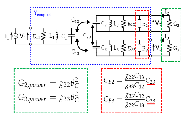
Figure 5: Optimal loads G2power and G3power are necessary to achieve maximum power transfer. Susceptances B2 and B3, given by the capacitances CB2 and CB3, are necessary to compensate the coupling between the receivers.
For achieving maximum efficiency, other values for the loads are necessary than for achieving maximum power transfer (Fig. 6). However, the same compensating capacitances are necessary to cancel the influence of the coupling between the receivers.
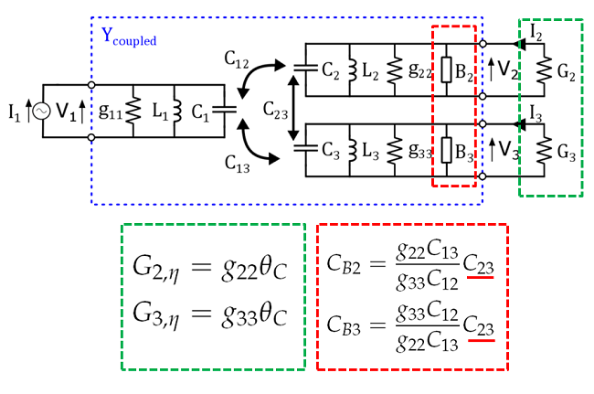
Figure 6: Optimal loads G2eta and G3eta are necessary to achieve maximum efficiency. Susceptances B2 and B3, given by the capacitances CB2 and CB3, are necessary to compensate the coupling between the receivers.
Fig. 7 shows the equivalent circuit for a capacitive wireless power transfer system with two transmitters and a single receiver. Again, a certain load G1opt is necessary to achieve maximum power transfer, as well as a parallel susceptance B1. However, now the compensating susceptance is an inductance, necessary to compensate for the coupling between both transmitters, given by the mutual capacitance C23.
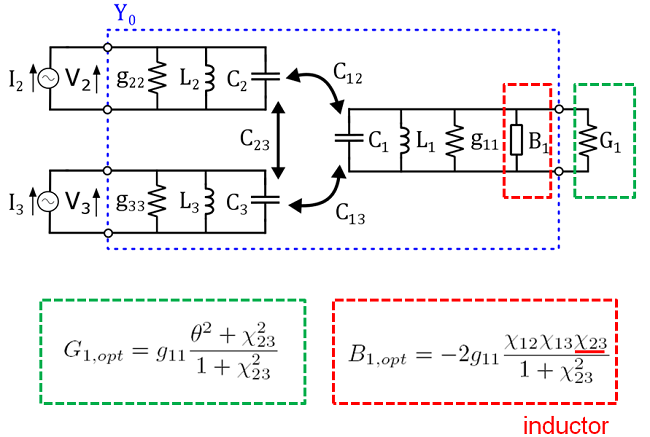
Figure 7: An optimal load G1opt is necessary to achieve maximum power transfer. Susceptance B1, corresponding with an inductance, is necessary to compensate the coupling between the transmitters.
Finally, we want the highlight the duality between capacitive wireless power transfer (CPT) and inductive wireless power transfer (IPT). Fig. 8 shows the dual expressions for a CPT system and IPT system with one transmitter and two receivers. For the details, we refer to the above references.
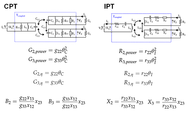
Figure 8: Duality between a capacitive (CPT) and inductive (IPT) wireless power transfer system with one transmitter and two receivers.